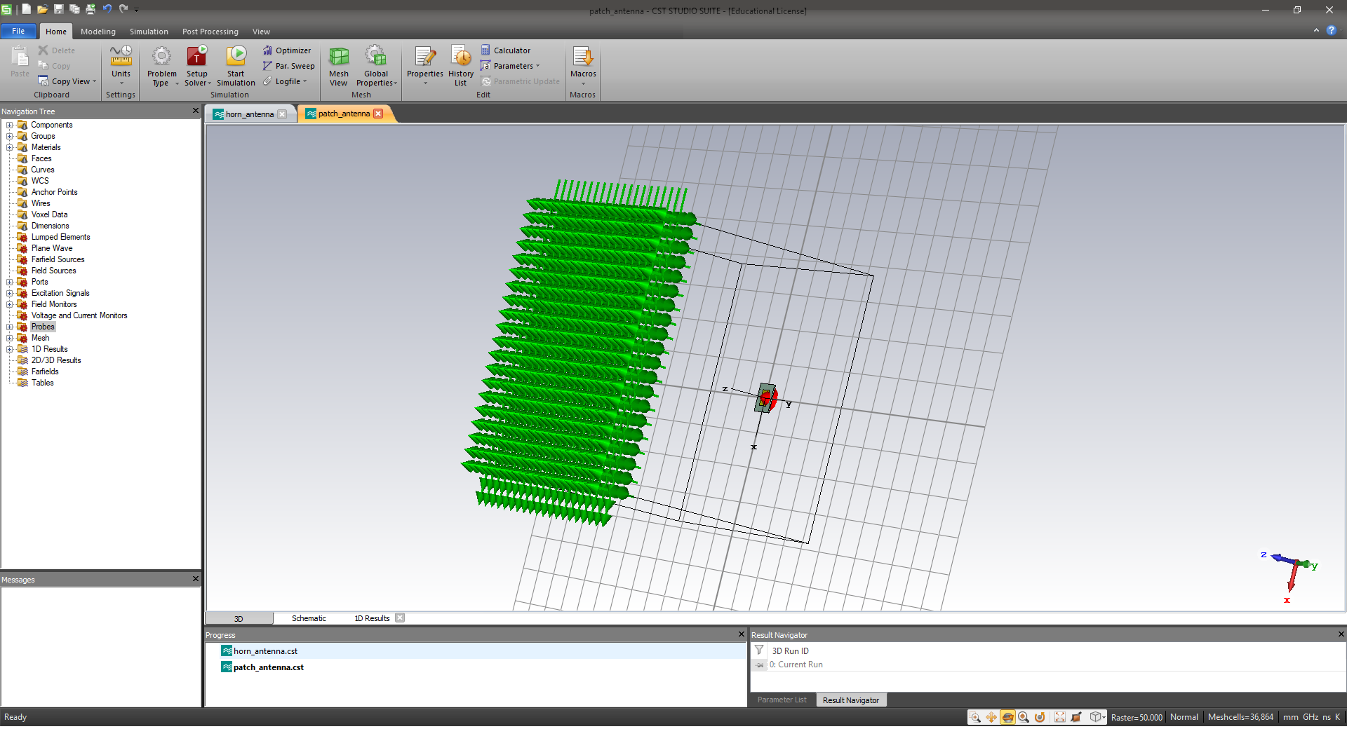

The frequency domain solver can simulate arbitrary infinite arrays using a unit cell.
 The features simultaneous excitation, combine results and farfield array offer a variety to find the best approach for a given problem. The array size is only limited by the available memory resources.
The time domain solver is a powerful tool for the simulation of finite antenna arrays. Summary Antenna array simulations with CST MICROWAVE STUDIO® Grating lobes occur at electrical Phase Shift Angles > 150 deg 15 Open-ended Waveguide Array Published results:īlind Spot occurs at an electrical Phase Shift Angle = 71 deg Scan angle definition (φ, θ) Infinite Arrays Unit Cell Definiton Single element:Īctive element pattern: TE TE := A00 cos −1 (θ ) 2 Units: mm, ghz Background: vacuum Boundaries: x,y unit cell (phase shift defined by angle of incidence) Ground plane: zmin Periodic port: zmax Bounding box: visible Simulation of a bigger array part necessary ¾ Different excitations easily realized by using the macro language for the Antenna Array featureĬoupling to next elements considered Infinite Arrays Unit Cell Project Template ¾ Recommended if Number of excitations > Number of elements ¾ Distributed Network Computing shortens the simulation time.įinite Arrays Farfield-Array ¾ No coupling between the simulated elements. ¾ Compute active SParameters/Impedances by given excitation and known S-Parameters. ¾ All desired amplitude/phase relationships between the ports can be easily calculated as a postprocessing step. ¾ Recommended if Number of elements > Number of excitations 8įinite Arrays Combine Results-Farfields ¾ Calculation of all ports and "combine results" in post-processing. ¾ Produces F-Parameter ¾ Phase shift valid for one frequency only. Switched Beam Approach: Switching between a finite number of predefined patternsĪdaptive Array Approach: Continuously adapting the pattern towards the optimal characteristic 7įinite Arrays Simultaneous Excitation ¾ Simultaneous port excitation with certain amplitude/phase relationships between ports. Goals: ¾Reduction of mechanical parts ❯lexible Resolution ¾Tracking of multiple objectsĪntenna Arrays for Communication Smart antennas Pattern optimization, Side lobe suppression – Circular Pattern Synthesis (Taylor, Bayliss ) – Planar Pattern Synthesis (Fourier, Schelkunov, Woodward, Dolph-Chebyshev, Taylor, modified sinc, Bayliss line source, Elliot iterative ). Beamforming, Blind spots, Coupling between elements, Active impedance. Mutual Coupling = Coupling from one element to others 4. Pattern Synthesis: Determine excitation function for the desired beam pattern. Scan = Phased excitation / change direction of incident wave. Element = One antenna element of the antenna array. Multiple beams: Channel capacity ~(N) Adaptive beamforming Reduced Multipath propagation Tracking of objects (e.g. Finite Arrays ¾ Simultaneous excitation ¾ Combine Results ¾ Farfield-ArrayĬhannel capacity ~log(N) Less expensive amplifiers.


